新規サイト003のヘッダー
engine-world
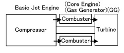
Engine Type 


| ① Piston Engine On December 17, 1903, the Wright brothers succeeded in their first powered flight with the Wright Flyer. The engine at that time was a "in-Line / water- cooled engine" that they made themselves. I wanted to know the engine that the great brothers thought, so I made a model with respect and a focus on functions. (seeRE-06) Additionally, I made the "Power Plant" Functional Model including Engine, Propeller, Reduction Drive Chain and Systems (Fuel, Water, Electrical, Instruments and Control) to explain the progressiveness of the Wright brothers. (SeeRE-06PP) 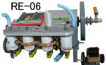 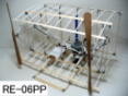 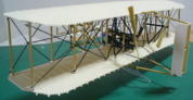 The engine installed in the 11 Bleriot aircraft that succeeded in "crossing the Strait of Dover", which was one of the triggers for the dawn, was a Semi- Radial 3-cylinder (W3) engine. I made that model. (SeeRE-08) In the 1910s (the dawn), when practical application of aircraft was started, the following three types of engines were used. (A) In-line Water-Cooled Engine (seeRE-03) (B) Radial Rotary, Air-Cooled Engine (seeRE-02andRE-05) (C) Radial, Water-Cooled Engine (seeRE-04) In particular, (B) and (C) have an interesting structure filled with the wisdom of predecessors over 100 years ago. Also there are unique configuration about "Valve Mechanism and Connecting Rod" for type (B). Please refer to "Here" for the "Major Feature Difference". 1927.5.21 Charles Lindbergh made a successful solo transatlantic flight on the "Spirit of St. Louis". His engine was a Radial, 9-cylinder. (seeRE-09) After that, with advances in materials (light alloys) and processing technology (A) has evolved into a V-shaped layout. (B) and (C) have evolved into the common Radial Engine. (seeRE-01) The cylinders were multi-rowed to improve power output. (seeRE-10) Most aircraft piston engines use the Poppet Valve mechanism (Cam, Tappet, Pushrod, Rocker arm, Valve spring, Valve), but I learned that engine was developed having the completely different mechanism named as "Sleeve Valve " in the 1930s to 1940s. (seeRE-07) The features of "Sleeve Valve" are said to be that the shape, size, and number of intake and exhaust valve ports can be ideally designed, and that the tapping noise of the Poppet Valve is eliminated. Many companies around the world tried to develop this feature, but it seems that only company "B" in the UK was able to put it to practical use. It seems that it was not in time for World War II, but it was used until the Korean War. I learned that this type of engine is still participating in air racing. I was also very interested and tried a functional model. When I made it, I felt that if the jet age was delayed, it might have jumped into the leading role of the piston engine. (seeRE-07) V-type, water-cooled, 12-cylinder engine was used in the stylish fighter (Spitfire, P-51 Mustang) that were active in World War II, which are called world-famous aircraft. (SeeRE-11) IIn addition to this upright type, the V type has the inverted type (RE-12) used for BF109 and 飛燕. Propellers are used for propulsion. Replaced to Jet engines for reasons such as weight, fuel costs, pollution, and life. However, small engines still use piston engines other than Radial-type. It is an interesting engine for studying mechanisms. Post-World War II, while jet aircraft appeared, engines of the type called Turbo Compound Engine that recover exhaust energy output by turbines were used in large aircraft such as DC-7, Constellation and P2V-7. This type was famous for Curtis-Wright R3350 engine, which incorporated many of the latest features of the time. This model (RE-13) was created as a teaching aid to explain its main features. At the same time, the C-124 Globemaster, B-50 Superfortress, H-4 Spruce Goose, etc. used engines with maximum displacement of 7 cylinders x 4 rows = 28 cylinders. It was a P&W R4360 engine. It was created as a teaching material (RE-14) to explain its characteristics. |
といい 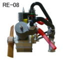 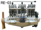 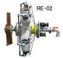 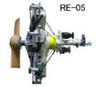 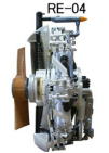 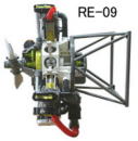 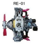 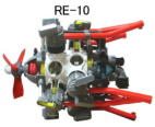 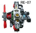 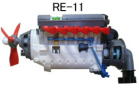 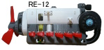 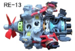 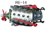 |
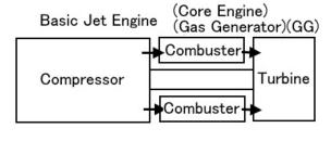
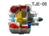
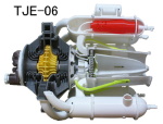
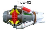
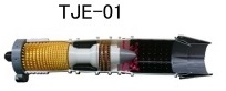
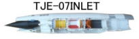
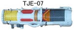
| → | Only exhaust power of Jet engine is used.....” Pure Jet” The world's first jet-propelled flight was achieved on August 27, 1939 with the "He178" equipped with the "HeS3B" engine by Dr. Ohain. 「TJE-05」 is the image model. The E28/39 powered by "W1" engine by Sir Whittle made its maiden flight on May 15, 1941. "TJE-06" is the image model. Sir Whittle together with Dr. Ohain was called "Jet Engine Pioneer" and made great contribution to the subsequent development of jet aircraft. Please refer to "Special Article ④" for a comparison of both engines. Centrifugal compressors were used in the 1st generation jet engines born in the 1940s and 50s. There is "Double-Sided Compressor" type and have been used in jet trainers for half a century. [TJE-02] is the image model. After that, axial compressors became mainstream. There is present on some fighters. [TJE-01] is a combination of a compressor and a turbine on one shaft. -It is called 1-Spool Engine) In the 1970s, the world's fastest practical aircraft that exceeded Mach 3 was born. It was achieved using a combination of Turbojet engines and Ramjet. For details, please refer to "TJE-07INLET" and "TJE-07". -(1 axis (spool) Engine). |
      |
| → | turn the "Fan” (inside of the engine case).....” Turbofan” The type of turbofan engine has been developed in which the intakeair is divided into the engine interior (core) and the engine exterior(fan) and mixed at the discharge section, including the improvementof jet engine efficiency and noise control. This will lead to the rapid development of the jetliner era. |
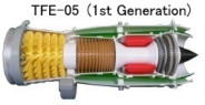 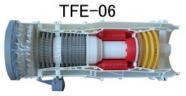 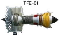 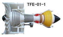   |
| The ratio of fan to core air volume is called the bypass ratio. In the 1st generation (1960s), the bypass ratio was around 1:1. (TFE-05) (TFE-06) After that, the bypass ratio has been increased for further efficiency, and the engine bypass currently used for jetliner is 4: 1 or more. (TFE-01) is used for Mid Class Passenger Airplane and (TFE-01-1) for Big Class one. Recently, there is the engine near 10:1bypass ratio. Based on the engine (TFE-07) that contributed to the twin-engine and two-pilot configuration of passenger aircraft, I have created a spool model that can explain the internal structure and function of the engine spool. (TFE-07Spool) ・ Secondary air system ・ Shaft/disk configuration ・ Bearings and related seals ・ Relationship between each spool -(2 axis (spool) Engine) (See TFE-05,TFE-06,TFE-01,TFE-01- 1,TFE-07) About "Main Bearings", SeeJEC-15. |
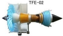
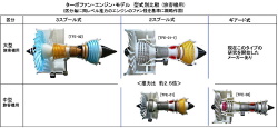
| There is also the engine that divides the compressor drive into two axes. In this type, there is the engine with bypass ratio of 11:1. -(3 axis (spool) Engine) (See TFE-02) |
 |
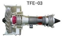
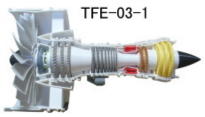
| Recently, there is also an engine that mounts a reduction gear between the fan and the turbine shaft to obtain efficient rotation of the fan and the turbine respectively. Some engines of this type have 12:1bypass ratio. -(Geared type Turbofan (GTF)) (See TFE-03) A large motor-driven model (10-inch fan) has been redesigned so that the difference in rotation between the LP turbine and the fan, which is a feature of this engine, can be seen. (SeeTFE-03-1) |
  |
||
| Image processing has been added for the current turbofans for passenger aircraft, based on the fan diameter, so that the features and differences of each model can be read. please refer. |
 |
||
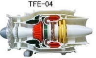
| 1st generation (1960s) turbofan engine and some small engines for business aircraft have fan air ducts extended to the rear. -(Full duct Turbofan) (See TFE-05,TFE-04) |
 |
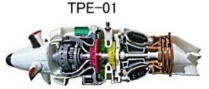
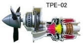
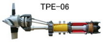
| → | turn the "Propeller"..... Turboprop It is no longer used for large commersial aircraft due to speed, noise, etc., but it is still used for military cargo aircraft. It is still widely used in business machines. There are "Direct Drive type" and "Free Turbine type". The engine in which the turbine, compressor and propeller are mechanically connected is called as "Direct Drive type". (SeeTPE-01andTPE-02) Among them, there is the model in which the Reduction Gear Box (RGB) is separated. It is still used in military cargo aircraft with over 4000 horsepower. (SeeTPE-06) |
   |
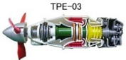
| The engine with the independent propeller drive turbine is called as " Free Turbine type". (SeeTPE-03) Both types are used for business aircraft. |
 |
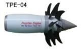
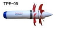
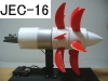
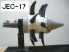
| "Future type engine" Research is underway to increase the speed to that of the turbofan engine while making good use of the fuel consumption of the turboprop engine. The angle of sweepback is given to the Contra (Counter)-Rotating Propeller (Fan) and it is calledPropfan, Open rotor, Un-ducted fan, and Ultra high bypass engine. (SeeTPE-04,TPE05) Please refer to "JEC-16" for an example of the Propfan structure of "Planetary Gear type"and "JEC-17" for an example of the Propfan structure of "Turbine type". There are many issues with these engines, and it seems that it will take some time before they can be put into practical use. The issues I felt through model making were ... ・ Shape and material of propfan ・ Pitch change mechanism for 10+ fans ・ ・ ・ Feather ← → Reverse is required ・ High power reduction gear mechanism ・ Noise reduction by counter-rotating fan ・ ・ ・ ・ etc. |
    |
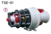
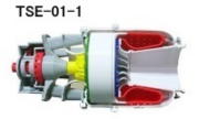
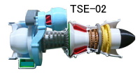
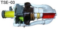
| → | turn the "Rotor"..... Turboshaft The engine is intended for rotational output, but is mainly used by helicopters to turn rotors through gearboxes. The models on the right are the compressor and turbine radial type, "TSE-01" is the running model and "TSE-01-1" is its cutaway model. There are also axial and free turbine engines. "TSE-02" is an example of a free turbine type. Helicopters require equipment to avoid inhaling foreign matter and dust. They are installed as part of the helicopter structure, but are rarely incorporated into turboshaft engines as part of the engine structure. This is called “Integrated Inlet Particle Separator (IPS)” and has a complicated structure."TSE-02" is a model of that. There is an engine that has been used all over the world as an engine for small helicopters since the 1960s. The main reasons for this are high performance, high maintainability due to reverse flow and modular design, and the degree of freedom of mounting on the aircraft. There is an example that it was actually installed at 45 degrees upward."TSE-03" is the model of this. In addition to turning the rotor, some engines are used only for the purpose of turning the aircraft generator and compressor. This is called the Auxiliary Power Unit (APU). This APU is mainly mounted on large aircraft and does not require the ground powered ehicle. |
    |
| → | Conversion to other industries Taking advantage of the high performance, light weight, short-start, and other features of the aero engine, the basic jet engine(gas-generator or core) part is used, and it is not limited to the turboprop and turbofan engines described above, but also turboshaft engines. As, it has been diverted to industrial engines. [Example] High-speed boat (Jetfoil, Patrol boat), Emergency generator |
 |
|