新規サイト003のヘッダー
engine-world
Ⅳ. Engine Basic Components 

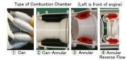
| Here, the following engine main components are described. ①Compressor ②Combustion Chamber ③Turbine ④Propeller ⑤Fan ⑥Planetary gear ⑦Variable nozzle ⑧Swivel nozzle ⑨Torquemeter ⑩Fuel nozzle ⑪Air Starter ⑫CVT-Toroidal type ⑬Bearing ⑭Coupling ⑮Oil Seal |
|
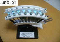
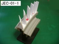
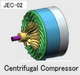
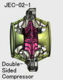
| ① Compressor It compresses the inhaled air, but there are two types, axial flow type and centrifugal type, depending on the shape of the blades. -Axial flow type It consists of inlet guide vanes, blades (rotating blade), and stators (stationary blade). Guide vanes and stator vanes are used with variable inflow angles according to the operating conditions. There are various methods to install the blade. "JEC-01" is the general "Axial Dovetail type". Advances in processing technology have created the rigid “Drum-type Disc” and the dovetail slot have become circumferential. Therefore, the installation of the blade has changed to the unique method. See "JEC-01-1". Small engines sometimes use rotors with an integral process (Precision casting or Machining) of disk and blade. -Centrifugal type It is made up of parts called impellers and parts called diffusers. This method is often found in small engines because it can obtain high compression ratio in one stage. For small engines, axial flow type is often added before centrifugal type. The first-generation jet engine also had a “Double-Sided Suction” type with the impellers back to back. [TJE-02] is an engine model that uses it. |
  |
  |
|
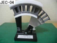
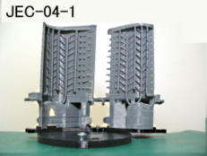
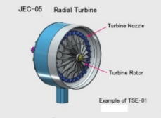
| ③ Turbine -Axial flow type Currently, the axial flow type is mostly used. The nozzle guide vanes and blades form the combustion gas passage. In addition, in order to prevent the gaps from expanding due to the thermal expansion of the rotor and blades, various measures are taken to improve efficiency, such as cooling the case. [JEC-04] is a model of those basic components of the turbine. The turbine inlet temperature greatly affects engine efficiency, so manufacturers are struggling to develop high-temperature materials and cooling methods. Some modern engines have turbine inlet temperatures that far exceed metal melting temperatures. The most severe high pressure turbine nozzles and blades have the precise and complex structure using various cooling techniques. Therefore, I made the model [JEC-04-1] that can understand the outline of the structure and manufacturing method of the latest high-pressure turbine blade. It also gives an overview of the manufacturing process using precision investment casting. -Radial flow (radial) type This type was found in early engines, but now it is slightly found in small APUs (auxiliary power units). |
  |
 |
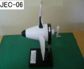
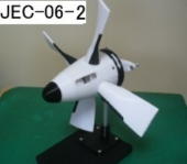
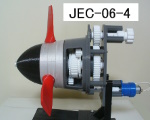
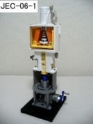
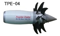
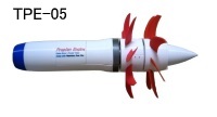
| ④ Propeller/Propfan The propeller is said to be efficient if it is up to about 6 to 700 kilometers per hour. Currently, constant-speed propellers that maintain constant rotation regardless of the speed of the aircraft are the mainstream. Therefore, the "propeller governor" is used to change the pitch according to the speed. Engine lubricating oil is used to change the pitch. Refer to "JEC-06-1". Also, as mentioned earlier, it is also possible to generate braking force by changing the pitch. When the engine is stopped in the air, it is possible to set the pitch close to 90°to reduce propeller resistance. This is called " Feathering". There are "link type" and "gear type" as typical examples of the pitch change mechanism. "JEC-06" is "link type" and "JEC-06-2" is "Ggear type". The "Counter-Rotating Propeller" has been developed for a long time to eliminate the "Anti-torque" generated by the propeller, but it has not been adopted in practical machines except in some countries from the viewpoint of weight, noise, etc. Please refer to "JEC-06-3" for an example of the structure. As mentioned above, engine oil pressure is mainly used for pitch change. However, in the "Inverted V-type 12-cylinder Engine" (seeRE-12) developed in Germany during World War II, hydraulic pressure could not be used because the motor-cannon were mounted in the propeller shaft, and the "Electric Propeller ” was used. A model was created to explain the structure and principle using the motor drive and differential gear. (seeJEC-06-4) Research is underway to increase the speed to that of the turbofan engine while making good use of the fuel consumption of the turboprop engine. The angle of sweepback is given to the Contra (Counter)-Rotating Propeller (Fan) and it is called Propfan, Open rotor, Unducted fan, and Ultra high bypass engine. Contra-rotating methods include gear type, planetary gear type, and turbine type. Many technical issues have not been put to practical use yet. Please refer to "JEC-16" for an example of the Propfan structure of "Planetary Gear type"and "JEC-17" for an example of the Propfan structure of "Turbine type". There are many issues with these engines, and it seems that it will take some time before they can be put into practical use. The issues I felt through model making were ... ・ Shape and material of propfan ・ Pitch change mechanism for 10+ fans ・ ・ ・ Feather ← → Reverse is required ・ High power reduction gear mechanism ・ Noise reduction by counter-rotating fan ・ ・ ・ ・ etc. For a sustainable world, I created a model of the futuristic airliner engine that I want. "JPE-07" I have organized the above series of models. “Special Article ⑥” |
    |
 |
  |
  |
 |
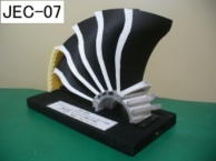
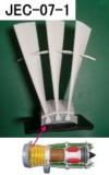
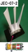
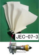
| ⑤ Fan Since the birth of the turbofan engine, various types of fans have been developed. Initially "Metal Fans" were the mainstream, but recently “Laminated Composite Material Wide Cord Blades” have come to be used. "JEC-07" is that model. The previous all metal fan blades were of the following types: "JEC-07-1" is the model with the Snubber (Midspan Shroud or Partspan Shroud) type fan. "JEC-07-2" is the model of Pin/Rivet type fan. The challenges for "Fan" are performance, weight reduction, bird- collision measures and scattered containment measures. Each manufacturer is struggling because of this contradictory measure. In recent years, the new concept fan has begun to be used in medium- sized engines (with 50-inch class fan). It is called "Blisk Fan". Blisk is the name for the rotor that combines the blade and the disk. Blades are manufactured by machining. Blisks have long been used in small and large engines for compressors that have short blades and do not need to be replaced on the field. This fan seems to have been born out of the new concept that puts priority on reducing the number of parts, reducing weight and improving efficiency over than maintainability. "JEC-07-3" is its image model. |
    |
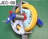
| ⑥ Planetary Gear This device is not limited to aviation engines, and is more widely used than before. It is an unobtrusive device but an integral device for Piston,Turboprop and Turboshaft engine. It is also used in geared turbofan (GTF) engines. Currently, it has begun to be used for large turbofan engines "TFE-03" It may be expanded in the future. It is also an essential device for the main gear box for helicopters. There is also type of Propfan engine currently under development that take advantage of the features of this device. This is also essential component to Air Starter"JEC-13". |
 |
 |
|
| ⑦ Variable Nozzle As mentioned in the "Air and Fuel" section above,theexhaustoftheengine contains a lot of unburned oxygen. The device that reburns this oxygen and increases the thrust is the "afterburner". If this device is operated, the back pressure of the engine will increase,and as it is, it may cause backflow inside the engine. Therefore, in the engine with "after burner",thevariablenozzleisattachedto the rear endandtheareaischangedaccordingtotheoperating condition. It is made of heat-resistant sheet metal and has a complex structure. There are cam & roller type, all link type etc. |
 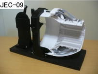 |
| ⑧ Swivel Nozzle Some state-of-the-art fighters have aircraft carriers landing vertically. Attached to the rear end of the engine is an exhaust duct called the 3-Bearing Swivel Nozzle (3 BSN). 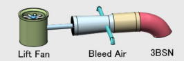 The movement is so complex that it is modeled to make iteasiertounderstand. 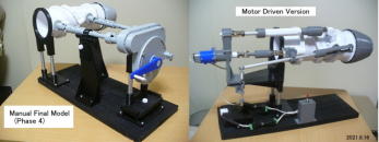 |
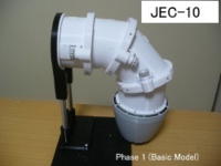 |
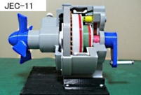
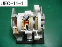
| ⑨ Torquemeter Engines that use rotational output (Turboprop, Turboshaft) incorporate the torque meter system that uses the opposite torque of the engine output. There are various methods, but in engines in which the engine and reduction gear are integrated, the one utilizing engine oil is often used. By replacing the anti-torque with axial movement and adjusting the opening of the valve, it balances the pressure in the piston and cylinder with the anti-torque axial force. Then, this pressure is displayed on the cockpit panel as the torquemeter and used to control the engine. As the method to generate that axial movement; 【Ⅰ】Planetary gear used spur gears(Carrier shaft is as the output shaft) Add the helical spline around the ring gear and use the axial force generated in the ring gear. This method provides a relatively large piston area, so engine oil pressure can be used. [JEC-11] is the model for this method. 【Ⅱ】Planetary gear used helical gears(Ring gear is as the output shaft) Use axial force generated on carrier gear (s). This method requires a higher pressure pump for torque meter because each piston area is narrow. 【Ⅲ】Reduction gear with the helical gear train(mainly for turboshaft engines) Use axial force generated on the intermediate gear. [JEC-11-1] is the model for this method. 【Ⅳ】Others Some engine use the difference in torsion between two or one shaft(hydraulic or electrical). |
  |
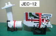
| ⑩ Fuel nozzle It is an important part to burn fuel energy without waste. The fuel nozzle is closely related to the combustion chamber to be attached. Its role is to provide a stable particle spray over a wide range from low output to high output. There are various types of fuel nozzles, but the current mainstream is "Spray type", Two types of are used. (1)Simplex fuel nozzle (2)Duplex fuel nozzle These atomization methods are nearly identical, the difference being single or double. The high-pressure fuel sent from the fuel system is distributed circumferentially in the nozzle and sprayed from the central injection hole via the swirl passage. Then, compressed air is introduced from the outer periphery of the nozzle to promote atomization, and unburned fuel is blown off when the engine is stopped to prevent carbon deposition. That is, the duplex fuel nozzle corresponds to the engine that supplies the primary fuel and the secondary fuel. The fuel nozzle is closely related to the combustor,butthemanufacturingtechnology is different, so it is manufactured by a specializedmanufacturer who specializes in precision parts. Parts with fine and precise holes are assembled in an overwrapping manner, but the surface is super-precision processed (lapped) to prevent leakage between the parts. [JEC-12] is to illustrate the basic internal structure of the "Duplex Fuel Nozzle". In addition, there are "Evaporator Tube type nozzle" and "Centrifugal type" which sprays using centrifugal force from the center of the rotor, used for the early engine. At present, research on new combustors and fuel nozzles is being conducted in various engines to further reduce pollution, and I think a completely new system will emerge. |
 |
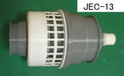
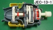
| ⑪Air Starter For “Mid” and “Large” class jet engine starting,theairturbinestarterisused to reduce weight than electric starter (motor). Air starter is drive by pressurized air supplying byAPUorgroundequipment. There are “Radial” or “Axial” type of turbine. This is “Axial”typerunningmodel by the home vacuum cleaner as the source of power.(SeeJEC-13) Cutaway for above is [JEC-13-1]. |
  |
| ⑫CVT-Toroidal type There are various types of CVT (Continuously Variable Transmission),but there are the following types of friction type. (1) Belt type using V-groove pulley ... Metal belts and chains etc. (2) Toroidal type that uses the donut-shaped roller Currently, the method of (1) is widely used in automobiles. (2)hasbeenused for several car models, but it seems that it has ended. These types of CVT are not used in the aero engine itself. However, I knew that the Toroidal CVT of (2) is used for anACgenerator(115V, 400Hz) calledIDG(Integrated Drive Generator),whichisanaccessory for the aircraft that is attached to the gearbox. Also it is called CSD (Constant Speed Drive). I wanted to know the basic structure and made a simple running model.(SeeJEC-14) |
 |
| ⑬Bearing Bearings are one of the key components of jet engines. This time, The bearing teaching material is created toexplaintheturbofanengine as an example. The large turbofan engine (2 spool type) currently in useconsistsof5main bearings. [SeeJEC-15] All 5 bearing models were created to explain the type, shared load,androle of each location. Not only the entire display but also each model can bepickedupandturned by finger. |
 |
| ⑭Coupling Parts(Curvic(R) Coupling, Involute Spline) To prevent vibration, the structure with high rigidity and thatdoesnotshift the rotation axis due to centrifugal force or thermalexpansionisused. Representative examples are shown in "JEC-18" and "JEC-19". |
  |
| ⑮Oil Seal Oil seals are important parts that prevent the oil used to lubricatethebearings from leaking into the air passages or to the outside.Representative examples (carbon, labyrinth, brush) used in themainbearing section are shown in "JEC-20". |
 |