H8/3664F - Network Analyzer
![]() Project Overview
Project Overview
![]() Hardware
Hardware
![]() Software (H8/3664F side - C program)
Software (H8/3664F side - C program)
![]() Software (PC side - VB5 program)
Software (PC side - VB5 program)
![]() Software Down Load
Software Down Load
![]() Reference
Reference
![]()
Updated on
December 10th, 2001 ---- Updated pictures
October 23rd, 2001 ---- Start the project
![]()


![]()
Network Analyzer ----- Overview![]()
![]()
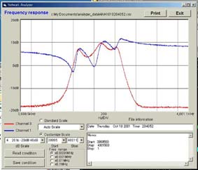
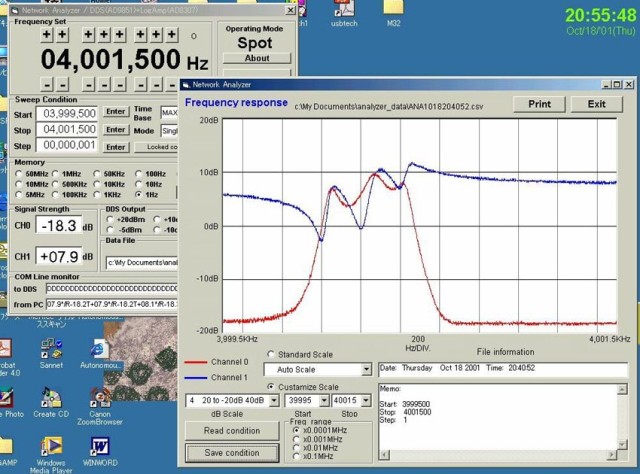
What does it do?
This network analyzer can measure frequency response of both passive circuit
and active circuit. For example, I made a ladder type Xtal filter using
three 4MHz crystal resonance. The following chart is a result of the filter
response. You can adjust a response curve to change capacitor value.
Target Specification for Network Analyzer
1.Signal Generator function
Frequency Range:
100KHz to 60MHz
Output level:
0.1Vp-p to 4Vp-p max.
Core Devices:
AD9851BRS
DDS(Direct Digital Synthesizer)
EL2075CN OP-Amp (2GHz Gain-Bandwidth)
Output:
Sin wave
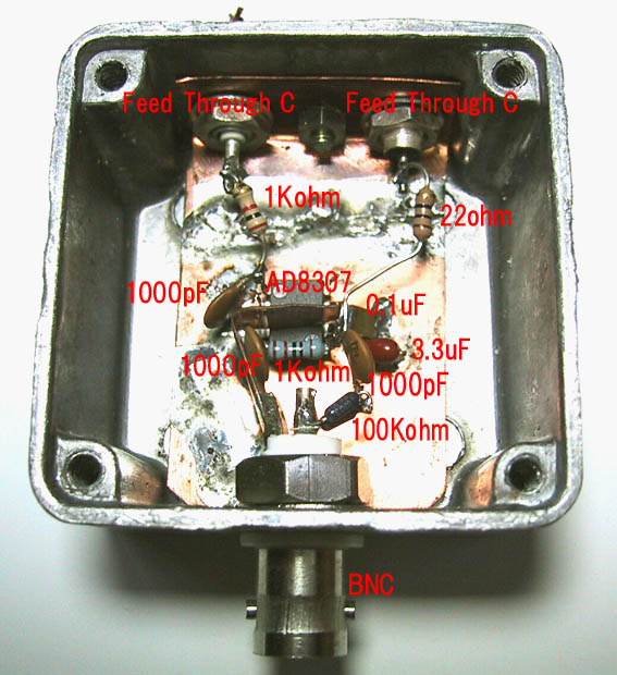
2.Signal Detectors
Core Device:
AD8307 DC-500MHz,92dB Logarithmic Amplifier
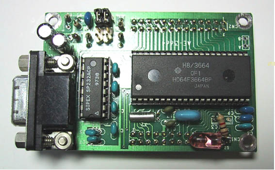
3.Controller
MPU:
H8/3664F
Memory:
External EEPROM 24LC64
EIA-232 interface for PC communication
PC control

Command for Control
Cmd Command format Function Example
H [H]
Show
Help massage Network Analyzer by Kenji Arai / JH1PJL Sep..,2001
F [F-0to9&AtoF(8chr)-*]
Set Frequency F00120345*
= 120.345KHz, F50123000* = 50.124MHz
D [D] Read
both Ref and Thru data Send "D" then receive
"R123T321*" (R=12.3dB, T=32.1dB)
A [A-0to3(1char)-*]
Set Amplitude of OSC. A1* = +10dBm (0=Max,1=+10dBm,2=0dBm,3=-10dBm)
S [S] Show
current data Send
"S" then receive "SFF50123000#R123T321#A123*"
T [T] Show
timer data Send "T"
then receive "T01234567*" Unit = mSec
P [P-0to9&AtoF(8chr)-*]
Set Frequency step F00120345* = 120.345KHz, F50123000* = 50.124MHz
+ [+]
Frequency up New
Freq = Current Freq. + Step Freq.
- [-]
Frequency down New Freq
= Current Freq. - Step Freq.
![]()
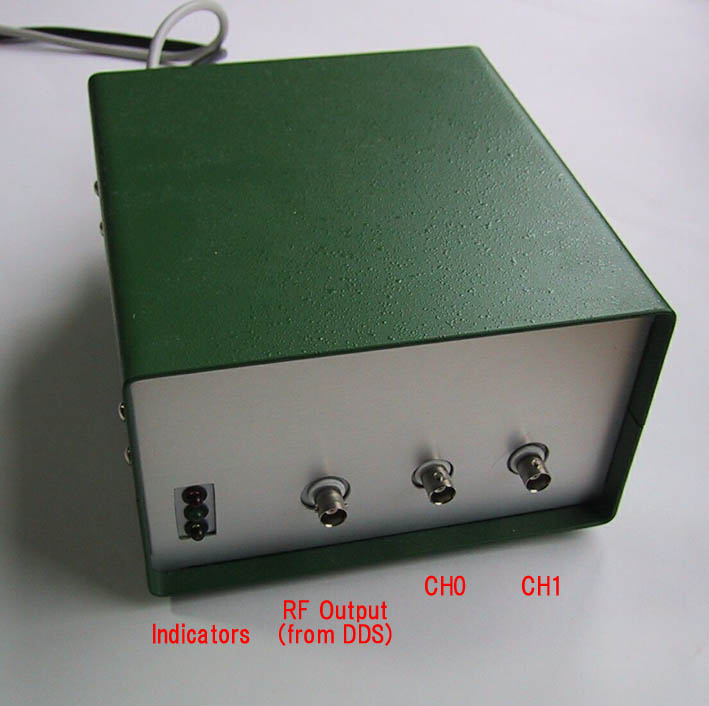
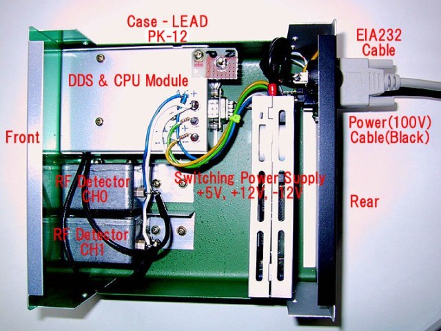
Network Analyzer ----- Hardware![]()
![]()
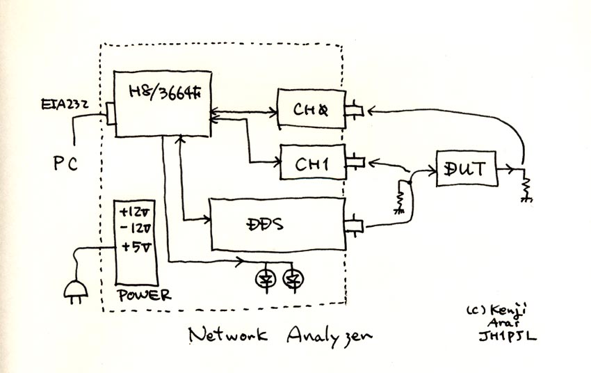
Circuit Structure
Circuit block diagram is here.
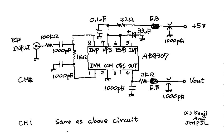
Log. Amp.
Here
DDS Circuit
Here
H8/3664F Pin
Assignment
Here
![]()
Network Analyzer ----- Software (H8/3664F - C program)![]()
![]()
Network analyzer program of H8/3664F side is very simple. A main subroutine
wait one character input from EIA232C serial interface then parse the character
and jump to proper job subroutine.
To keep accuracy of a data measurement, the network analyzer has a compensation
data inside of H8 code space. The data calibrates by Signal Generator made
by Wavetek. The followings are compensation data.
/* -----< Data Table >------------------------------------------------
*/
const unsigned long TbL_Freq[TBLNOFREQ] = {
100000, 500000, 1000000, 5000000, 10000000, 20000000,
30000000, 40000000, 50000000, 60000000, 70000000 Frequency table
};
const int Tbl_dB[TBLNODB] = {
100, 0, -100, -200, -300, -400, -500 dB data (real =1/10)
};
ADC measured data
const long Tbl_ch0[TBLNODB][TBLNOFREQ] = { First channel
{1460,1508,1560,1584,1650,1750,1807,1831,1826,1864,1864}, 10dB
100K, 500K, 1M , 5M , 10M, 20M, 30M, 40M, 50M, 60M, 70M
{1189,1246,1303,1332,1398,1489,1546,1569,1569,1607,1603}, 0dB
{ 937, 989,1051,1075,1137,1232,1289,1322,1317,1360,1355}, -10dB
{ 666, 732, 794, 823, 880, 980,1037,1065,1070,1108,1103}, -20dB
{ 328, 471, 523, 552, 614, 713, 780, 851, 808, 842, 837}, -30dB
{ 228, 271, 300, 319, 347, 461, 518, 547, 552, 590, 580}, -40dB
{ 224, 228, 228, 233, 238, 271, 304, 319, 319, 347, 347} -50dB
};
const long Tbl_ch1[TBLNODB][TBLNOFREQ] = { Second channel
{1465,1508,1560,1584,1650,1750,1807,1836,1855,1826,1845},
{1194,1251,1303,1332,1398,1493,1541,1569,1598,1579,1584},
{ 951, 994,1051,1075,1137,1227,1284,1322,1346,1327,1336},
{ 675, 747, 799, 818, 885, 980,1037,1070,1099,1080,1089},
{ 333, 476, 533, 556, 614, 713, 780, 813, 842, 823, 828},
{ 238, 276, 304, 323, 361, 466, 518, 552, 580, 556, 571},
{ 224, 228, 233, 233, 243, 276, 309, 323, 342, 328, 338}
};
Program
/****************************************************************************
Network Analyzer.c
Programmed by Kenji Arai/JH1PJL
E-mail: kenjia@sannet.ne.jp jh1pjl@arrl.net
URL: http://www.page.sannet.ne.jp/kenjia/
August 16,2001 Start new proj. using H8/3664,AD9851 &
AD8307
October 8,2001 1st Version
October 28,2001 Homepage version
Copyright (C) 2001 Kenji Arai/JH1PJL
All rights reserved. Permission is granted to use, modify,or redistribute
this software so long as it is not sold or exploited for profit.
THIS SOFTWARE IS PROVIDED AS IS AND WITHOUT WARRANTY OF ANY KIND,
EITHER EXPRESSED OR IMPLIED.
****************************************************************************/
/* Original article was on the QST magazines (Jan.& Feb.,1998)
*/
/* ================================================================== */
/* ===== Network Analyzer PIC Interface Program
===== */
/* ===== By: Steve Hageman 12Jan97
===== */
/* ================================================================== */
/* Hardware */
/* AKI-3664 Tiny Micom (H8/3664F 42Pin SDIP)
*/
/* ----- Include Files ---------------------------------------------- */
#include "3664f.h"
#include "sci.h"
#include "ad9851.h"
Skip source code
/* -----< Data Table >------------------------------------------------
*/
Compensation data for real dB level (Using Signal Generator reference level)
const unsigned long TbL_Freq[TBLNOFREQ] = {
100000, 500000, 1000000, 5000000, 10000000, 20000000,
30000000, 40000000, 50000000, 60000000, 70000000 Frequency Table
};
const int Tbl_dB[TBLNODB] = {
100, 0, -100, -200, -300, -400, -500 Real data is 1/10
};
Freq. V.S. dB level
const long Tbl_ch0[TBLNODB][TBLNOFREQ] = { Channel #1
{1460,1508,1560,1584,1650,1750,1807,1831,1826,1864,1864},
{1189,1246,1303,1332,1398,1489,1546,1569,1569,1607,1603},
{ 937, 989,1051,1075,1137,1232,1289,1322,1317,1360,1355},
{ 666, 732, 794, 823, 880, 980,1037,1065,1070,1108,1103},
{ 328, 471, 523, 552, 614, 713, 780, 851, 808, 842, 837},
{ 228, 271, 300, 319, 347, 461, 518, 547, 552, 590, 580},
{ 224, 228, 228, 233, 238, 271, 304, 319, 319, 347, 347}
};
const long Tbl_ch1[TBLNODB][TBLNOFREQ] = { Channel #2
{1465,1508,1560,1584,1650,1750,1807,1836,1855,1826,1845},
{1194,1251,1303,1332,1398,1493,1541,1569,1598,1579,1584},
{ 951, 994,1051,1075,1137,1227,1284,1322,1346,1327,1336},
{ 675, 747, 799, 818, 885, 980,1037,1070,1099,1080,1089},
{ 333, 476, 533, 556, 614, 713, 780, 813, 842, 823, 828},
{ 238, 276, 304, 323, 361, 466, 518, 552, 580, 556, 571},
{ 224, 228, 233, 233, 243, 276, 309, 323, 342, 328, 338}
};
/* -----<< Main >>----------------------------------------------------
*/
void main()
{
initialize();
opning_msg(); PC opening massage
/* Main loop */
while(!DOOMSDAY)
{
/* Wait for EIA232 char -> parse to command */
LED_COMM = OFF;
Buf = SciGetC(0); Waiting for one input char. from PC
LED_COMM = ON;
switch(Buf){
/* Send Help massage */
case '?': {
goto job_H;
}
case 'H': {
goto job_H;
}
case 'h': {
job_H:
SciPutC('/');
help_msg();
SciPutC('*');
break;
}
/* Frequency set Parser */
case 'F': {
goto job_F;
}
case 'f': {
job_F:
LED_FCHG = ON;
SciPutC('/');
set_dds_freq_direct(); Set DDS freq.
LED_FCHG = OFF;
break;
}
/* Frequency step set Parser */
case 'P': {
goto job_P;
}
case 'p': {
job_P:
LED_FCHG = ON;
SciPutC('/');
set_dds_freq_step(); Set Step freq. data
LED_FCHG = OFF;
break;
}
/* Data transfer Parser */
case 'D': {
goto job_D;
}
case'd': {
job_D:
SciPutC('/');
data_send(); dB Data send to PC (Two channel data)
SciPutC('*');
break;
}
/* Set Amplitude of DDS */
case 'A': {
goto job_A;
}
case 'a': {
job_A:
SciPutC('/');
set_dds_amp(); Set DDS output condition
break;
}
/* Show current data */
case 'S': {
goto job_S;
}
case 's': {
job_S:
SciPutC('/');
set_all_data(); Show all setting condition
SciPutC('*');
break;
}
/* Show timer data */
case 'T': {
goto job_T;
}
case 't': {
job_T:
SciPutC('/');
show_timer(); Display current time from power on
SciPutC('*');
break;
}
/* Frequency UP */
case '+': {
goto job_UP;
}
case ';': {
job_UP:
SciPutC('/');
freq_updwn(0); New freq. = current freq. + step freq.
SciPutC('*');
break;
}
/* Frequency DWON */
case '-': {
goto job_DWN;
}
case '=': {
job_DWN:
SciPutC('/');
freq_updwn(1); New freq. = current freq. - step freq.
SciPutC('*');
break;
}
/* Check Conection */
case ' ': {
SciPutC('/');
break;
}
/* Not in command list */
default: {
/* Error */
SciPutC('!'); Ireagal command
}
LED_RUN = ON;
} /* End of switch */
} /* End of while */
} /* ----- End of main ----- */
/* -----<< Subroutines >>---------------------------------------------
*/
/* -----<< Interrupt >>-----------------------------------------------
*/
/* TIMERV Initialize routine */
void reset_timerV()
{
}
/* TIMERV Interrupt Handler */
void timerV_irq()
{
}
![]()
Network Analyzer ---- Software(PC side - VB5 program)
![]()
![]()
VB5 program structure is consisted following forms
FormNtWrk_Anlyzr(anlyzr_H8.frm)
This is a main form. It has following functions.
Communication with PC
DDS frequency setting
Frequency sweep Data display
frmAbout(anlyzr_H8_about.frm)
Form for Version display
frmFileFind(frmFileFind.frm)
Form for data file display if the data is saved in a disk. You can see
measured date and memorandum. So you can identify easily.
frmFreqChart(frmFreqChart.frm)
Form for frequency chart. Y axis is dB data for RF signal strength and
X axis is frequency data. Frequency span is adjusted automatically and
can set manually if you want
frmTip(frmTip.frm)
Form for choosing file save function.
FromFileControl(FromFileControl.frm)
Form for file save condition setting. Default data format is CSV.
![]()
Network Analyzer ----- Software Down Load
![]()
![]()
H8/3664 Control program
-------- Anlyzr_H8_Software
VB5 PC program
-------- Anlyzr_VB_Software
![]()
Network Analyzer ----- Reference
![]()
![]()
Componets information
H8/3664F
http://www.hitachisemiconductor.com/sic/resource/japan/jpn/pdf/mpumcu/j602071_h8300hpm.pdf
http://www.hitachisemiconductor.com/sic/resource/japan/jpn/pdf/mpumcu/j602223_h83664.pdf
http://www.renesas.com/eng/products/mpumcu/16bit/tiny/3664/index.html
http://japan.renesas.com/fmwk.jsp?cnt=product_folder.jsp&fp=/products/mpumcu/h8_family/h8300h_tiny_series
DDS Chip(AD9851BRS) & AD8307
http://www.analog.com/
http://www.analog.com/en/prod/0,,770_843_AD9851%2C00.html
http://products.analog.com/products/info.asp?product=AD9851
http://www.analog.com/en/prod/0,,770_847_AD8307%2C00.html
http://products.analog.com/products/info.asp?product=AD8307
EL2075
http://www.intersil.com/cda/home/
http://www.intersil.com/data/fn/fn7151.pdf#search='EL2075'
http://www.elantec.com/
Article
1998.1 and 2 QST Hageman
Feb 1998 Build Your Own Network Analyzer? Part 2, by Steve Hageman, p 35. Windows 3.1/95 operating program and the
source code
---- hageman.zip
http://www.arrl.org/files/qst-binaries/
Gokan
http://www.picfun.com/appframe.html
![]()