C8051F300 (Silicon Laboratories)
![]() Overview
Overview
![]() Hardware
Hardware
![]() Software
Software
![]() Software Down
Load
Software Down
Load
![]() Reference
Reference
![]() Acceleration sensor
input
Acceleration sensor
input
![]() PWM setup for
Servo Motor
PWM setup for
Servo Motor
![]()
Updated on
May 18, 2002 ----
Added G-sensor and PWM explanation
![]()
May 14, 2002
---- Started the project
![]()
C8051F300 / Overview
![]()
![]()
Related information
Cygnal
http://www.cygnal.com/default.htm
We can reach following site as Silicon Laboratories Inc.
http://www.silabs.com/tgwWebApp/public/index.htm
http://www.silabs.com/products/microcontroller/mlp_matrix.asp
Development Environment
I have following "Development kit".
http://www.silabs.com/tgwWebApp/public/web_content/products/Microcontrollers/en/C8051F300DK.htm
http://www.silabs.com/products/microcontroller/C8051F300DK.asp
Example project
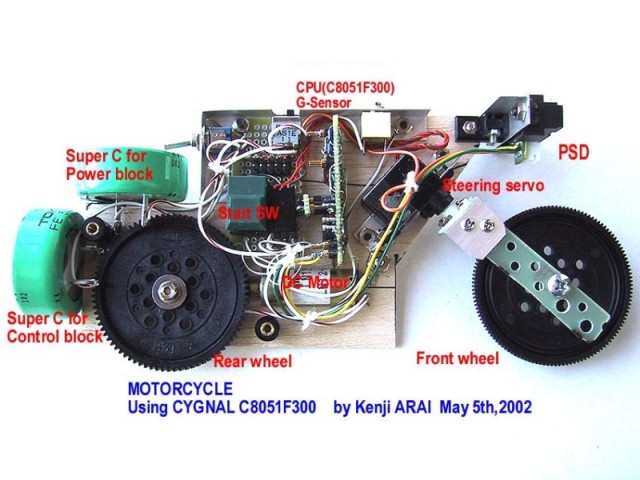
I made miniature
Motorcycle as an application but I couldn't finish it yet.
Basic
Function
Control items are;
・ Control for driving force by small DC motor
・ Control for steering by servo motor
For this purpose, following devices are used as sensors.
・ PSD sensor for detection of front obstructions
・ X-Y axes acceleration sensor for trim
control
In addition for this;
・ Monitoring function by radio transmitter
All of this functions are controlled by C8051F300.
![]()
C8051F300/ Hardware
![]()
![]()
Hardware
structure
You can reach a circuit drawing as below.
Circuit Diagram(2 pages)
C8051F300 is in very small package so it's
very difficult to handle. I recommend to use DIP type
evaluation chip for amateur hobby purpose. You cannot
see 3mm x 3mm chip in the picture.
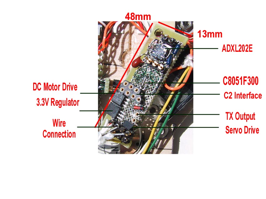
CPU has a clock oscillator in the chip so you don't need
any additional circuit and pins for the clock.
I'm using acceleration sensor made by ANALOG DEVICES, ADXL202E. This is also very small only 4.5mm x 5mm. ADXL202E
outputs PWM pulse as acceleration related data. F300 has PCA
module (Programmable Counter/Timer Array) for three
independent channels. In the project, two channels are used
for PWM data input from ADXL202E as input capture function
and another channel is used for 16Bit PWM Output as
steering servo motor control.
F300 ADC is used for PSD(Sharp GP2D12) input. PSD output
voltage range is from 0V to 2.6V. Every 38.3mS (typ.), PSD is
updating output. So I set 20mS sampling time for PSD data
processing but this is very slow sampling time because F300
has 500ksps capability.
Power consumption point of view, PSD is not so good because
it spends 50mA (max.). DC motor is only 10mA (no load
condition) and F300 and ADXL202E are only fee mA.
Wireless serial communication is not regular application.
This is just for your reference.
I use AM-RT5-418(AM Hybrid
Transmitter - RF Solutions) and AM-HRR3-418(AM Hybrid Receiver). It recommends 2400bps but
I used it as 9600bps speed.
![]()
C8051F300 / Software![]()
![]()
I'm using Keil C compiler for
Software development. F300DK includes both hardware (evaluation
board) and Keil software.
I couldn't finish the development (and never end ?) but
followings are temporary results.
(a) PSD signal processing using ADC function
(b) Acceleration detection using
G-sensor siganl to F300 PCA function
(c) Servo motor control using PCA PWM function
(d) DC motor speed control
using F300 TIMER2 function
(e) Data transmit
function using F300 UART0 and wireless TX module
C8051F300
Know-How (Programming tips)
(a)PCA 16bit Software Timer
F300/1/2/3 manual
said in page 137;
Important Note About Capture/Compare Register: When writing a
16-bit value to the PCA0 Capture/Compare registers, the low
byte should always be written first.
C compiler creates two byte code by opposite byte order.
If I write C-code as below;
if ( CCF2 == 1){
// -------- Module 3 ------------------------
if ( pwm_period
== 0 ){
PCA0CP2
= pwm_data;
}
CCF2 = 0; // For just in
case
}
Keil C compiler creates following assembler code. This cannot
follow the rule.
MOV PCA0CP2+01H,pwm_data
MOV
PCA0CP2,pwm_data+01H
Then, I need to modify the source code as below.
if ( CCF2 == 1){
// -------- Module 3 ------------------------
if ( pwm_period
== 0 ){
PCA0CPL2
= (unsigned char)pwm_data; // Set center position of servo data
PCA0CPH2
= (unsigned char)(pwm_data/256); //
(need separate loading method !)
}
CCF2 = 0; // For just in case
}
Code is created as below.
MOV PCA0CPL2,pwm_data+01H
MOV A,pwm_data
MOV
PCA0CPH2,A
This is okay. But I spent half day to recognize it.
(b)
Priority Clossbar Decoder
This is also very important point to use F300
function. Points are;
・ F300 has crossbar
function and need to recongnize which is via a crossbar which
is NOT via clossbar
・ Need clear definition
of each resources (UART,SMBus,SYSCLK,CP0
Output,PCA,T0&T1 and Port Latch data)
It very simple rule but during the debugging, it is very
difficult to judge function setting miss or crossbar setting
miss.
![]()
C8051F300 / Software Down Load![]()
![]()
Control program for C8051(not finished yet)
------- Motocycle
![]()
C8051F300 / Reference
![]()
![]()
Please see overview area
![]()
C8051F300 / Acceleration sensor
input
![]()
![]()
Data sheet(ANALOG DEVICES-ADXL202E) mentioned calculation method for
acceleration sensor as follows.
//
ADXL202 Acceleration data
// |<---data-->|
// |<---------period-------->|
(data/period) - 50%
// _________
________ g = ------------------------------
// |
|
|
12.5%
// ___|
|________|
// t1
t2
t3
(PCA0 counter data)
//
// Overflow process is ignored ( only once is expected)
//
PCA0 module sets input capture mode with both rising and
falling edge then measure free running counter data at t1, t2
and t3 timing ( you can see those part in the below as BLUE PART).
Free running counter is 16 bit length so it becomes overflow
condition. Easy programming method is to match the data
length of F300 PCA and PWM output of ADXL202E. ADXL202E
has an adjusting function using Rset resister value change.
PCA0 clock sets as below.
void PCA0_Init (void)
{
PCA0CN = 0x40; //
Enable PCA counter
PCA0MD = 0x09;
// Sysclk/1, Enable Overflow int.
//
overflow = 2^16 * 1/(24.5 * 1e6)
// = 2.675mS
PCA0CPM0 = 0x31;
// Module0,
//
Both edge mode, enable interrupt
PCA0CPM1 = 0x31; // Module1,
// Both edge mode, enable
interrupt
PCA0CPM2 = 0xcb;// 16bit
PWM mode, comparator function
// Enable interrupt
// PCA0CP2 = SRV_CNTR; // Center position of
servo data
PCA0CPL2 = SRV_CNTR;
PCA0CPH2 = SRV_CNTR/256;
pwm_period = SRV_CNT_N;
}
This is maximum speed for the CPU. Rset is 200K ohm then PWM
base period is;
period = Rset/125Mohm = 200kohm/125Mohm = 200 *1e3 / 125 * 1e6
= 0.0016 [sec] = 1.6 [msec]
I measured raw data from acceleration sensor using following
test program.
void show_acc_data( void )
{
unsigned int dt0, dt1;
if ( x_ready == 1){
EA = 0; // disable
interrupts
dt0 = x_period;
dt1 = x_data;
EA = 1; // re-enable
interrupts
PutCRLF(); // Display T = xxxxmS
PutStr("Txp= ");
// show_time_data( dt0 );
show_time_data( x_period );
PutStr("d= ");
// show_time_data( dt1 );
show_time_data( x_data );
}
x_ready = 0;
if ( y_ready == 1){
EA = 0; // disable
interrupts
dt0 = y_period;
dt1 = y_data;
EA = 1; // re-enable interrupts
PutCRLF(); // Display T = xxxxmS
PutStr(" Typ= ");
// show_time_data( dt0 );
show_time_data( y_period );
PutStr("d= ");
// show_time_data( dt1 );
show_time_data( y_data );
}
y_ready = 0;
}
void show_time_data( unsigned int dt )
{
putchar(dt/10000 +'0'); // 10^4
dt = dt - (( dt / 10000 ) * 10000);
putchar(dt/1000 + '0'); // 10^3
dt = dt - (( dt / 1000 ) * 1000);
putchar(dt/100 + '0'); // 10^2
dt = dt - (( dt / 100 ) * 100);
putchar(dt/10 + '0'); // 10^1
putchar(dt%10 + '0'); // 10^0
PutStr(" mS ");
}
Using this program, I calculated
measured data as Here. Average data is 36,893.
period = 36893 * (2.675msec/ 2^16) = 36893 * (2.675*1e-3/65536)
= 36893 * 40.817 * 1e-9 = 1505.87 [usec] = 1.506 [msec]
If I use this value, free running counter overflow is zero or
once per measurement. Then we don't need to consider overflow
itself. We can just calculate it using unsigned 16bit
data.
static unsigned int
t1_x, //
Rising edge data for starting
t2_x, // Falling edge data
t3_x, // Rising edge data for ending
t1_y, // Same rule as X-axis
t2_y,
t3_y;
void PCA0_ISR (void) interrupt 9 using 3
{
if ( CF == 1 ){ //
-------- PCA0 Overflow -------------------
deleted;
}
if ( CCF1 == 1 ){ //
-------- Module1 -------------------------
if (X_IN == 1){ //
Measure rising edge data
t3_x = PCA0CP1;
// Read caputure data from
Module0
x_period = t3_x - t1_x;
// Calculate cyclic time
x_data = t2_x - t1_x;
// Calculate acceleration data
t1_x
= t3_x;
// Save data for next mesurement
x_ready = 1; //
Set ready flag
} else { //
Mesure falling egde data
t2_x = PCA0CP1;
// Read caputure data from
Module0
}
CCF1 = 0;
// Clear interrupt source
}
if ( CCF0 == 1 ){ //
-------- Module2 --Same as Module1 -------
deleted;
Normalization is in here as "calcu"
sheet.
//------------------------------------------------------------------------------------
// Normalization of Acceleration Data
//------------------------------------------------------------------------------------
// G = (data/period
-50%) / 12.5% [G]
// = (data/period * 100 - 50) / 12.5 [G]
// = (data/period * 100 - 50) * 1000 / 12.5 [mG]
// = (data/period * 100 * 1000 - 50 * 1000) / 12.5 [mG]
// = data * 1000 * 10 / period * 100 / 125
- 50*1000 / 12.5 [mG]
// = data * 10000 / period * 100 / 125 -
4000 [mG]
//
void nor_acc_data( void )
{
unsigned int dt0, dt1;
if ( x_ready == 1){
EA = 0; // disable interrupts
dt0 = x_period;
dt1 = x_data;
EA = 1; // re-enable interrupts
x_g =(int)((unsigned
long)dt1 * 10000L / (unsigned long)dt0 * 100 / 125) - 4000;
}
x_ready = 0;
if ( y_ready == 1){
EA = 0; // disable interrupts
dt0 = y_period;
dt1 = y_data;
EA = 1; // re-enable interrupts
y_g =(int)((unsigned
long)dt1 * 10000L / (unsigned long)dt0 * 100 / 125) - 4000;
}
y_ready = 0;
}
Collection of normalized data is here (Sheet 0429_data_1 & 0429_data_2). Result is below.
X1
Y1 X2
Y2
Ave -75.37
-1082.40 870.33 -185.28
Shiguma 6.83 7.70 8.21 10.62
Max -60.00 -1058.00
897.00 -161.00
Min -113.00
-1105.00
848.00 -219.00
Diff
53.00 47.00
49.00
58.00
EXPECTED
DATA 0.00 -1000.00 1000.00 0.00
![]()
![]()
C8051F300
/ PWM setup for Servo Motor
![]()
![]()
I'm using following servo motor.
・Company: Grand Wing Servo-tech Co.,Ltd.
・Web:
http://www.grandwing.com(I couldn't reach the Web site)
・Type: PICO F/BB
Neutral position needs 1500 microS active pulse width. PCA0
cannot set clock source three channels independently. PCA0
already uses for PWM input capture for acceleration sensor.
So PCA0 Channel #1 also needs to use same clock and use for
16bit PWM output. Servo motor is well designed for only affect
active pulse width. We can keep cyclic period around 15mS to
20mS.
Cyclic period is controlled by software with rough accuracy. RED PART is PWM setting and BULE PART is overflow control.
void PCA0_Init (void)
{
PCA0CN = 0x40; //
Enable PCA counter
PCA0MD = 0x09;
// Sysclk/1, Eable Overflow int.
// overflow = 2^16 * 1/(24.5 * 1e6)
// = 2.675mS
PCA0CPM0 = 0x31; // Module0,
// Both edge mode, enable interrupt
PCA0CPM1 = 0x31; // Module1,
// Both edge mode, enable interrupt
PCA0CPM2
= 0xcb;// 16bit PWM mode, comparator function
// Enable interrupt
// PCA0CP2 = SRV_CNTR;
// Center position of servo data
PCA0CPL2 = SRV_CNTR;
PCA0CPH2 = SRV_CNTR/256;
pwm_period = SRV_CNT_N;
}
PWM data is only for active pulse width as mentioned before.
Max and Min data is very important for the servo motor
because over range will be made a damage for plastic gear in
the motor. I broke one servo motor during debugging. You are
better to minimize following data as small as you can.
#define SRV_CNTR 36750 // 1.5mS * 24.5MHz = 39200
counts
#define SRV_MIN 19600 // 0.8mS * 24.5MHz = 19600
counts
#define SRV_MAX 58800 // 2.4mS * 24.5MHz = 58800
counts
Following is debug program. PSD data connects servo motor
data then you can check with you hand front of PSD.
//------------------------------------------------------------------------------------
// Show ADC data
//------------------------------------------------------------------------------------
// Vref = VDD = 3.28V
// Scale = 3.28 * 255/256 /256 [V/bit]
// = 3.28 * 255/256 /256 * 1000 * 1000 [mV/bit]
// = 12813 *255/256 [mV/bit]
// = 12763 [mV/bit]
//
void show_anlg_data( void )
{
long volt_dt; // ADC data (mV)
unsigned int dt;
EA = 0; // disable
interrupts
volt_dt = acc_ana;
EA = 1; // re-enable
interrupts
volt_dt = (volt_dt * 12763L) / 64000L;
show_volt_data( (unsigned int)volt_dt );
// ********** DEBUG *********** //
dt = SRV_MIN + (unsigned int)volt_dt * 14;
if ( dt > SRV_MAX ){
dt = SRV_MAX;
} else if ( dt < SRV_MIN ){
dt = SRV_MIN;
}
pwm_data = dt;
}
Overflow condition is controlled by following program.
#define SRV_CNT_N 6
// Servo PWM cycle counter
void PCA0_ISR (void) interrupt 9 using 3
{
if ( CF == 1 ){ // -------- PCA0
Overflow -------------------
if
( pwm_period == 0 ){
pwm_period = SRV_CNT_N;
} else {
pwm_period--;
}
CF = 0;
// Clear Overflow flag
}
if ( CCF1 == 1 ){ // -------- Module1
-------------------------
deleted;
CCF1 = 0;
// Clear interrupt source
}
if ( CCF0 == 1 ){ // -------- Module2 --Same
as Module1 -------
deleted;
CCF0 = 0;
}
if ( CCF2 == 1){ // -------- Module 3
------------------------
if ( pwm_period == 0 ){
PCA0CPL2 = (unsigned char)pwm_data;
// Set center position of
servo data
PCA0CPH2 = (unsigned char)(pwm_data/256);
// (need separate loading method !)
// PCA0CP2 = SRV_CNTR;
// Don't use this
command !!
} else {
PCA0CPL2 = 0; // Set
center position of servo data
PCA0CPH2 = 0; // (need
separate load !)
}
CCF2 = 0; // For
just in case
}
}
In the program, six interval is counted (RED PART) then if it's zero, PWM interrupt is enable to
set active pulse (BLUE
PART). We can set 19mS (2.675mSec
* 7 = 18.725mSec).
![]()
![]()